
Norman Hansen, CTO & Co-Founder
In this paper, we show how and why very early fault-injection tests greatly improve the speed and quality of the development process of safety-critical embedded systems. After a brief introduction to fault-injection testing for safety-critical systems using standards from the automotive domain as a guideline, the benefits of early-stage tests are highlighted. The third section focusses on fault-injection testing on the model level, with the fourth section giving a use-case example for model-based fault-injection testing using Mindmotiv’s Arttest as the testing environment.
1 Fault-Injection Tests and Software Safety
Fault-injection tests are tests of a system where the system’s reaction to an implausible or broken environment or even non-functional parts of the system itself are verified. For instance, a fault-injection test of a drive-by-wire application could check how the system behaves if there is unintended noise on the bus-system used. Another example is a test where cable connections are lost.
For safety-critical applications, their safety is to be guaranteed at any time. As such, these systems need to be tested considering any reasonable cause of failure, which is why fault-injection tests are crucial to ensure safety even under unplanned circumstances.
The ISO26262, a derivative of the IEC65108 norm for the automotive domain, does recommend the application of fault-injection tests for any Automotive Safety Integrity Level (ASIL). For the most safety critical systems, labeled as ‘ASIL D’, fault-injection tests are highly recommended.
| Methods | ASIL | ||||
| A | B | C | D | ||
| 1a | Requirements-based test | ++ | ++ | ++ | ++ |
| 1b | Interface test | ++ | ++ | ++ | ++ |
| 1c | Fault injection test | + | + | + | ++ |
| 1d | Resource usage test | + | + | + | ++ |
| 1e | Back-to-back comparison test between model and code, if applicable | + | + | ++ | ++ |
The main issue with fault-injection tests is that they are difficult to perform. In many cases, fault-injection tests are executed on the hardware level, when software and hardware are both available and the development process is therefore in an advanced stage (and errors are very costly to remedy). Moreover, fault-injection tests on hardware require either specific capabilities of the hardware test bench or (potentially dangerous) manual interaction, e.g., by literally unplugging a wire.
Thus, late-stage fault-injection testing is very expensive due to the need for more complex hardware test benches on the one hand, and time and resources to be expended for error correction very late in the development process on the other.
2 The Benefits of Early Testing
In “classic” software development processes, testing is in many cases a task that is performed only after development of a system or its components. It is obvious that safety-critical systems need to be tested when product development is completed, i.e., software components and hardware are completely integrated.
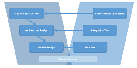
However, many processes, e.g., when following the V-model as shown below, also recommend tests of single components for different development stages, such as module tests, integration tests and finally system tests. These additional actions make validation more feasible by breaking down the complexity of the whole system and limiting the scope of the element(s) under test.
Further benefits of tests on multiple development levels are increased confidence in the system’s safety and the reduction of costs due to early error detection. As an example, let us consider a project in which the detection of a critical failure occurs at the very end of the development process. To remove it, the development team would have to find out whether there is a problem in one of potentially dozens of software or hardware components, the communication or interfaces between these components, or even with the requirements themselves.
Early testing is the solution to not only reduce the complexity of searches for causes of failures in large-scale systems, but to avoid them completely. If failures already occur on the component level, there is no need to search for causes in the integrated system. Moreover, early detection of software failures limits the search for the defects to the software since no hardware is involved.
For model-based development processes – with model creation, software generation and, finally, hardware integration – early testing is even more beneficial. Failures detected on the software level, but caused by defects in the model, are already quite difficult to identify since generated code needs to be matched to model elements. It is even more difficult and time-consuming to analyze the cause of a failure if the software is already running on target hardware and the failure is detected during hardware tests. If the cause of the failure is an error in the model, this error needs to be identified, traced back to the model, and resolved, potentially introducing new problems that require another full circle of debugging if tests are only done on hardware.
Thus, it is highly beneficial to perform as many tests as early as possible during the development of safety critical model-based developed embedded systems.
3 Fault-Injection Tests on the Model Level
In section 1 we discussed fault-injection tests as a necessary activity in the development of standard-compliant safety-critical systems that are often performed very late on the hardware level. In section 2, however, we showed that early-stage tests are not only easier to perform but also require less effort for fault detection and removal. Thus, an approach that combines both fault-injection and early-stage testing will not only mitigate the problems of “classic” fault-injection testing but lead to better product quality and save development resources at the same time.
In a modern model-based development process, the model is the earliest executable artefact. It can be simulated before any software code is generated and compiled or hardware is available. Consider a Matlab/Simulink model and a corresponding toolchain, for instance:
To perform a fault-injection test on a Matlab/Simulink model, four steps are required:
- Define the shape of the fault, e.g., constant zero, noise, specific unintended values or error codes.
- Drive the system to the state it should be in when the fault occurs.
- Inject the fault into the model at the location where the fault has an impact.
- Evaluate if the system still behaves as intended, i.e., if it fulfills the specified safety requirements.
Step 1 defines the shape of the signal (or signals), i.e., the values to inject into the system. There are multiple ways to specify these: graphically, textually or in table form as time-value pairs. They differ in the available tooling and functionality for the specification of signal values but generally all can be used with Matlab/Simulink via suitable export formats.
Step 2 seems to be the simplest step since the simulation environment performs the simulation to reach a certain state of the model. However, the desired precondition might be a state requiring the stimulation of the model with specific input signals. Thus, specification of signals driving the model to the state and application of the specification to model inputs is required. Moreover, one needs to know the exact timing of reaching the desired state or require a mechanism to detect the state and only then trigger step 3.
Step 3 relates to the injection of the fault itself. The tester needs to define one or multiple locations, e.g., scalar signals or elements of matrix or bus signals, in the model which are replaced by the faulty signals described in step 1. Besides the selection of the location in the model, a switching mechanism is required to change from simulated behavior to injected fault signals. Apart from the elements necessary to realize such mechanisms for fault-injection tests, the model under test should not contain elements introduced for testing purposes only, since they are not required in final product and would thus increase model and code size and potentially reduce performance if executed.
Finally, step 4 concerns the evaluation, like in any other test. After simulation, recorded signal values of interest need to be evaluated to ensure the actual behavior of the system complies with the expectation and the safety requirements.
With these four described steps in mind, section 4 will show how the required effort to perform fault-injection tests on the model level can be heavily reduced by tool-support to a level comparable to standard unit tests.
4 Fault-Injection Tests with Mindmotiv Arttest
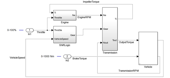
Arttest is a best-in-class testing environment that supports a wide variety of testing activities, among which are fault-injection tests on software models. Arttest addresses all four steps required for fault-injection testing by extensive tool-support. Let’s look at an example of a shift-logic controller similar to the MathWorks Automatic Transmission Controller. The ShiftLogic controller is integrated into an environment model consisting of a Transmission, an Engine and an abstract Vehicle as shown on the figure below.
Consider a fault-injection test of the closed-loop model where the engine revolutions-per-minute (RPM) measurement fails, i.e., the EngineRPM signal shall be overridden with invalid/implausible data, for example -1.
With Arttest, this test can be performed in very little time: first, the tester creates a project and a test for the model under test. The necessary test-harness is generated automatically by Arttest. Next, input stimuli for the signals Throttle and BrakeTorque are defined to force the model into the desired state before fault-injection. Arttest’s text-based signal-description concept provides multiple language elements to describe even complex signal curves in a single line and assists the tester with modern IDE features such as syntax checks, context-sensitive auto-completion, syntax highlighting, a live graphical signal preview, and more. To keep the example simple, let’s specify a constant Throttle value of 50% and 0 for the BrakeTorque.
Inputs
    <Throttle>    [50]    % apply throttle to start driving
    <BrakeTorque> [0]     % do not apply the brake
Specifying input signals in Arttest
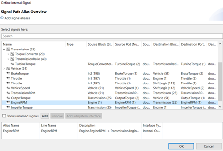
To inject “faulty behavior” into the model during simulation, a location in the model is selected and an alias, to easily address the signal at this location inside the test, is specified.
The faulty behavior to inject for the alias can now be specified in the test, similar to the specification of input stimuli. In the example, the signal EngineRPM is overridden. The injection of the fault is triggered by usage of the action “override on”. When the test reaches the override action, signal values from the EngineRPM simulation are switched to the values defined for EngineRPM in the test until an ”override off” action is reached or the test ends.
Step Start:
    wait for {0.5} seconds

Step RPMBreakdown: % override the simulated EngineRPM signal with -1
    override <EngineRPM> on
    <EngineRPM> set to  [-1]
    wait for {0.5} seconds
Fault-injection: overriding EngineRPM after 0.5 seconds with -1
To evaluate whether the fault-injection test succeeded or failed, Arttest’s powerful evaluation and assertion mechanisms are used. The desired behavior of arbitrary signals of the model can thus be expressed by using a reference signal specification with tolerances, e.g., for shifts in time or discrepancies in value:
    % tube evaluation with time and value tolerance from reference signal
    <VehicleSpeed> [0] (TUBE;.005;.08;0;.1)
    % expected gear is 1, use sequential evaluation without tolerances
    <Gear> [1] (SEQ;0;0)
Specification of a tube evaluation for VehicleSpeed with tolerances and a sequence evaluation without tolerances for the Gear signal
Criterion Start:
    % expect the speed to increase while the RPM sensor is working
    <VehicleSpeed> ramps to [9.5] within {0.5} seconds

Criterion RPMBreakdown:
    % expect no further change of VehicleSpeed or Gear due to broken RPM sensor (no change in value is the default assumption, no code required)
Specification of the expected reference behavior of VehicleSpeed
If desired, assertions in the form of arbitrary Matlab expressions can be used to check whether the model behaved as required. In this example, the tester simply checks that neither Gear nor VehicleSpeed increase after the faulty EngineRPM signal is inserted even though the Throttle is still at 50%.
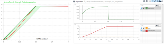
The left side of the graph above shows the evaluation result with the dark green signal being the specified reference signal for VehicleSpeed. The light green area around the reference signal is the area covered by the specified tolerances, i.e., deviations from the reference in time and value that are considered acceptable. The red line shows the actual recorded values of the signal during simulation.
As we can see, a fault-injection test on the model level can be achieved very quickly and easily with just a few lines of Arttest’s test specification language. The combination of the signal override action with sophisticated language constructs such as conditions and events as triggers for fault-injection enable a large variety of test scenarios, and tool-support for highly automated test creation, execution, evaluation, and report generation presents a strong case for model-based functional testing in general.
5 Summary
Fault-injections tests are highly recommended and thus should be performed. However, due to the overhead that fault-injection testing causes without suitable tool-support, it is usually not performed at optimum efficiency. By performing fault-injection tests as early as the model level, substantial effort, time, and costs can be saved thanks to earlier and faster error identification and removal without unnecessary debugging cycles. With Arttest, Mindmotiv provides a powerful and efficient testing environment for Matlab/Simulink models that enables embedded experts to exploit all these benefits with net negative effort. The extensive tool-support and integration into the test environment allows manifold ways to perform and combine fault-injection tests, e.g., in closed-loop or integration models, with ease.